


本文转载自维基百科:
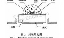
覆晶技术(Flip-Chip),也称“倒晶封装”或“倒晶封装法”,是芯片封装技术的一种。此一封装技术主要在于有别于过去芯片封装的方式,以往是将芯片置放于基板(chip pad)上,再用打线技术(wire bonding)将芯片与基板上之连结点连接,而覆晶封装技术是将芯片连接点长凸块(bump),然后将芯片翻转(flip)过来使凸块与基板(substrate,board)直接连结而得其名。
Flip Chip 技术起源于1960年代,是IBM 开发出之技术。IBM最早在大型主机上研发覆晶技术[1]。由于覆晶比其它BGA封装在与基板或衬底的互连形式要方便的多,目前覆晶技术已经被普遍应用在微处理器封装,而且也成为绘图、特种应用、和电脑芯片组等的主流封装技术,借助市场对覆晶技术的推力,封装业者必需提供8吋与12吋晶圆探针测试、凸块增长、组装、至最终测试的完整服务。
步骤
- 集成电路是在晶圆上创建
- 脚垫芯片表面金属化
- 焊接点上沉积每个垫
- 芯片被切割
- 芯片是翻转和定位,使焊球正面临着外部电路的连接器
- 然后重熔焊球(通常使用热风回流焊 )
- 安装的芯片是“底部填充的” 使用电气 绝缘胶


未来电子产品持续朝向轻薄短小、高速、高脚数等特性,以导线架为基础的传统封装型态将渐不适用,应用范围也将局限于低阶/低单价的产品。根据IC Insights的调查报告显示,逻辑IC产品由于功能要求日益复杂,对于封装引脚数的需求,大致呈现每年12%~13%的增加速率。以高阶的ASIC产品为例,2002年最高引脚数需求为2,100脚,而预计至2007年,最大引脚数将高达3,500脚。在未来覆晶封装的趋势上,依然会朝着高脚数(I/O),细间距(fine pitch)的目标前进。此外,未来除了覆晶封装设备的需求将持续扩大外,覆晶所需之检测设备亦是厂商发展的重点。由于覆晶封装内部是利用凸块作为电气通导路径,分布范围整个芯片,位于芯片中心附近的凸块品质检测,则有赖自动化检测设备以确保凸块品质,而由于覆晶封装的高脚数特性,单片探针数可达1,000pin以上的垂直探针卡,将成为测试设备商竞逐的潜力市场。
his article is about the semiconductor mounting technique. For the DEC trademark, see Flip Chip (trademark). For the CPU format, see Flip-chip pin grid array.
Flip chip, also known as Controlled Collapse Chip Connection or its acronym, C4, is a method for interconnecting semiconductor devices, such as IC chips and Microelectromechanical systems (MEMS), to external circuitry with solder bumps that have been deposited onto the chip pads. The solder bumps are deposited on the chip pads on the top side of the wafer during the final wafer processing step. In order to mount the chip to external circuitry (e.g., a circuit board or another chip or wafer), it is flipped over so that its top side faces down, and aligned so that its pads align with matching pads on the external circuit, and then the solder is flowed to complete the interconnect. This is in contrast to wire bonding, in which the chip is mounted upright and wires are used to interconnect the chip pads to external circuitry.
Contents[hide]
|
Process steps
- Integrated circuits are created on the wafer
- Pads are metalized on the surface of the chips
- Solder dots are deposited on each of the pads
- Chips are cut
- Chips are flipped and positioned so that the solder balls are facing the connectors on the external circuitry
- Solder balls are then remelted (typically using hot air reflow)
- Mounted chip is “underfilled” using an electrically-insulating adhesive
Comparison of mounting technologies
Wire bonding/Thermosonic bonding

The interconnections in a power package are made using thick aluminium wires (250 to 400 µm) wedge-bonded
In typical semiconductor fabrication systems chips are built up in large numbers on a single large wafer of semiconductor material, typically silicon. The individual chips are patterned with small pads of metal near their edges that serve as the connections to an eventual mechanical carrier. The chips are then cut out of the wafer and attached to their carriers, typically via wire bondingsuch as Thermosonic Bonding. These wires eventually lead to pins on the outside of the carriers, which are attached to the rest of the circuitry making up the electronic system.
Flip chip

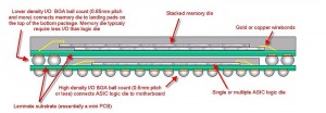
Side-view schematic of a typical flip chip mounting
Processing a flip chip is similar to conventional IC fabrication, with a few additional steps.[1] Near the end of the manufacturing process, the attachment pads are metalized to make them more receptive to solder. This typically consists of several treatments. A small dot of solder is then deposited on each metalized pad. The chips are then cut out of the wafer as normal.
Recently, high-speed mounting methods evolved through a cooperation between Reel Service Ltd. and Siemens AG in the development of a high speed mounting tape known as ‘MicroTape.'[1]. By adding a tape-and-reel process into the assembly methodology, placement at high speed, typically 20,000 placements per hour are achievable using standard PCB assembly equipment.[citation needed]
To attach the flip chip into a circuit, the chip is inverted to bring the solder dots down onto connectors on the underlying electronics or circuit board. The solder is then re-melted to produce an electrical connection, typically using an ultrasonic or alternatively reflow solder process. This also leaves a small space between the chip’s circuitry and the underlying mounting. In most cases an electrically-insulating adhesive is then “underfilled” to provide a stronger mechanical connection, provide a heat bridge, and to ensure the solder joints are not stressed due to differential heating of the chip and the rest of the system.
Advantages
The resulting completed flip chip assembly is much smaller than a traditional carrier-based system; the chip sits directly on the circuit board, and is much smaller than the carrier both in area and height. The short wires greatly reduce inductance, allowing higher-speed signals, and also conduct heat better.
Disadvantages
Flip chips have several disadvantages. The lack of a carrier means they are not suitable for easy replacement, or manual installation. They also require very flat surfaces to mount to, which is not always easy to arrange, or sometimes difficult to maintain as the boards heat and cool. Also, the short connections are very stiff, so the thermal expansion of the chip must be matched to the supporting board or the connections can crack.[2] The underfill material acts as an intermediate between the difference in CTE of the chip and board.
History
The process was originally introduced commercially by IBM in the 1960s for individual transistors and diodes packaged for use in their mainframe systems.[3] DEC followed IBM’s lead, but was unable to achieve the quality they demanded, and eventually gave up on the concept. It was pursued once again in the mid-90s for the Alpha product line, but then abandoned due to the fragmentation of the company and subsequent sale to Compaq. In the 1970s it was taken up by Delco Electronics, and has since become very common in automotive applications.
Alternatives
Since the flip chip’s introduction a number of alternatives to the solder bumps have been introduced, including goldballs or molded studs, electrically conductive polymer and the “plated bump” process that removes an insulating plating by chemical means. Flip chips have recently gained popularity among manufacturers of cell phones, pagers and other small electronics where the size savings are valuable.[citation needed]
See also
- Solid Logic Technology
- IBM 3081
References
- ^ Solder Bump Flip Chip
- ^ Demerjian, Charlie (2008-12-17), Nvidia chips show underfill problems, The Inquirer, retrieved 2009-01-30
- ^ Introduction to Flip Chip: What, Why, How
Further reading
- Wikihowto: Guide to IC packages


《【扒一扒】日本高纯球形硅微粉材料生产商》: 作为一种无机非金属矿物功能性粉体材料,硅微粉广泛应用于电子材料、电工绝缘材料、胶黏剂、特种陶瓷、精密铸造、油漆涂料、油墨、硅橡胶等领域。 目前,世界上只有中国、日本、韩国、美国等少数国家具备硅微粉生产能力... 全文 ?